built with concourse
OVERVIEW
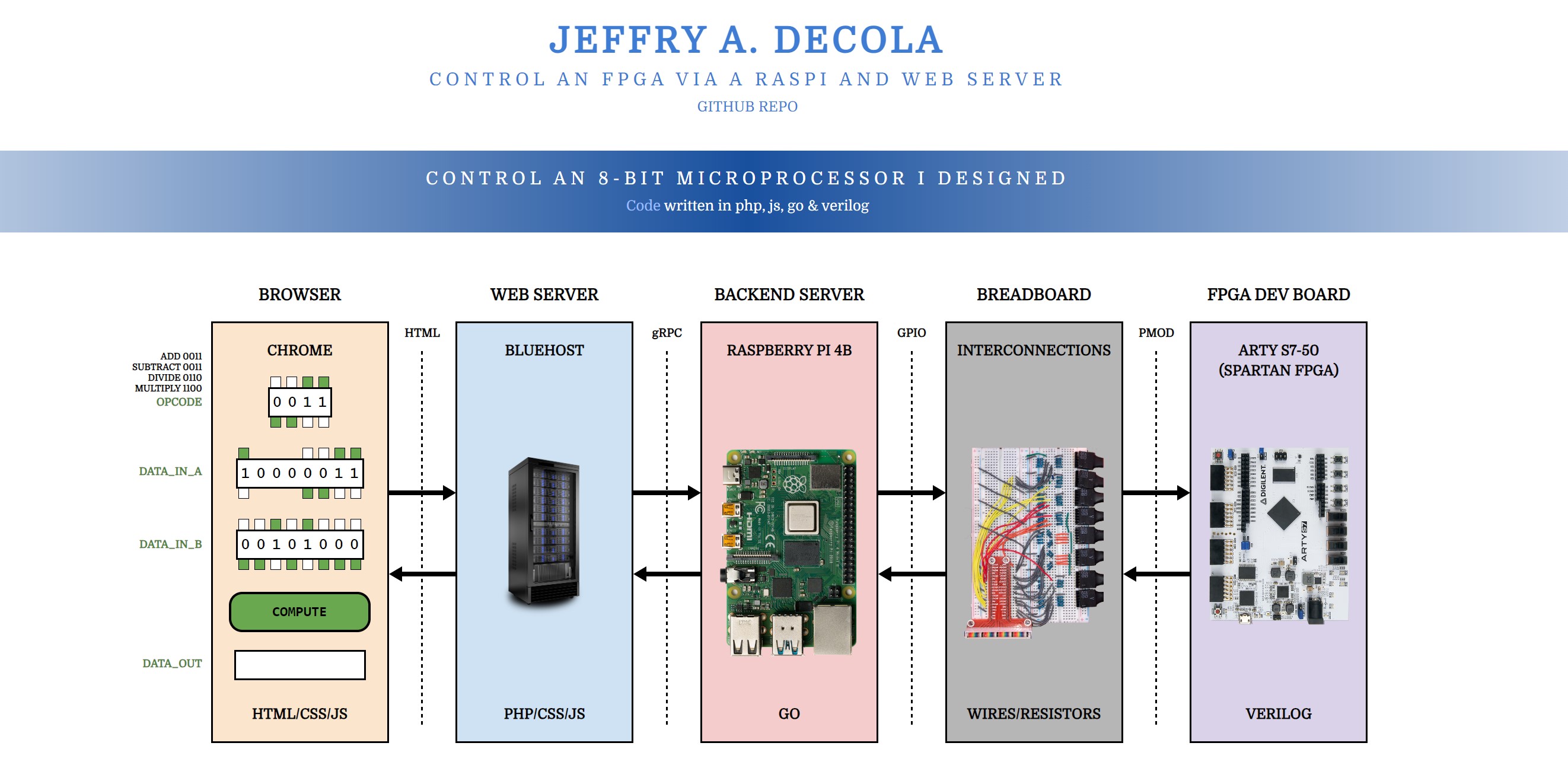
I burned my programable 8-bit microprocessor to an FPGA development board and you can control it at jeffdecola.com/control-an-fpga._
This project is separated into 5 main sections,
- I The FPGA (Digilent ARTY S7-50)
- II The BREADBOARD
- III The BACKEND SERVER (Raspberry Pi 4B)
- IV The WEB SERVER (Bluehost)
- V The BROWSER
This may help,
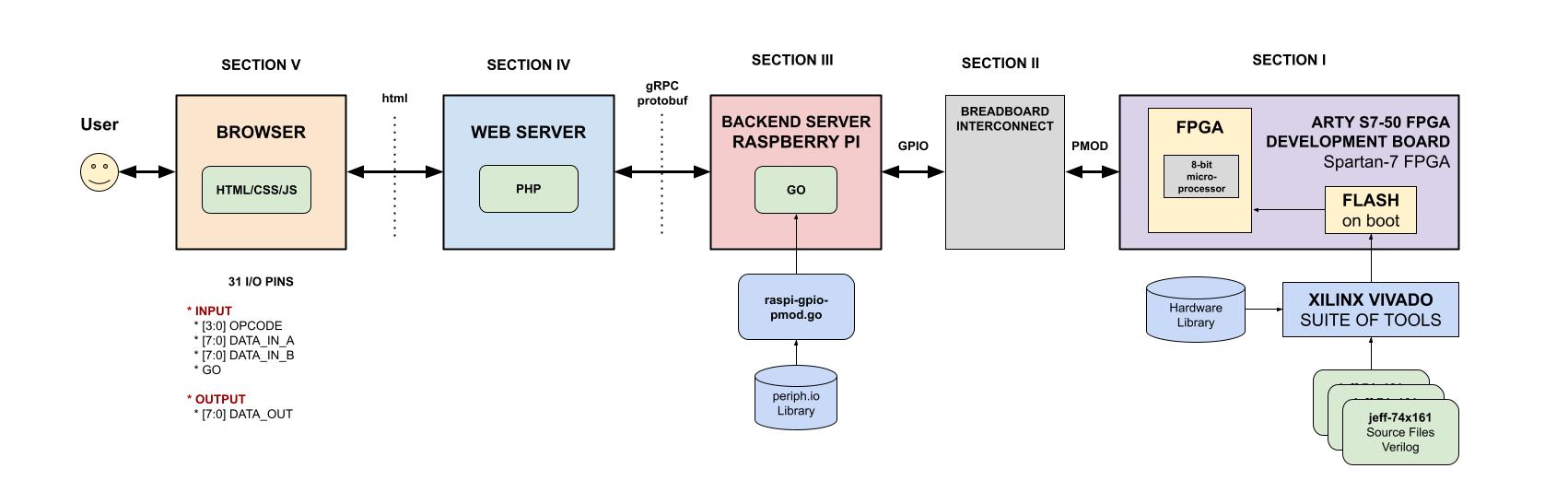
SOFTWARE/HARDWARE STACK
- SECTION I - The FPGA
- SECTION II - The Breadboard
- Connectors, resistors and wires
- SECTION III - The Backend Server
- SECTION IV - The Web Server
- php
- bluehost
- SECTION V - The Browser
- js
- html
- css
SECTION I - THE FPGA
Summary,
- I designed my programable 8-bit microprocessor in Verilog (An HDL language)
- I used the Xilinx Vivado IDE to synthesize and burn/flash the FPGA
- I used the Digilent ARTY-S7 FPGA development board
FPGA (MY 8-BIT MICROPROCESSOR)
I designed a programable 8-bit microprocessor in verilog and burned to an FPGA. Refer to that repo on how I accomplished this.
VERILOG
This is the high level architecture of the 8-bit microprocessor I designed in verilog,
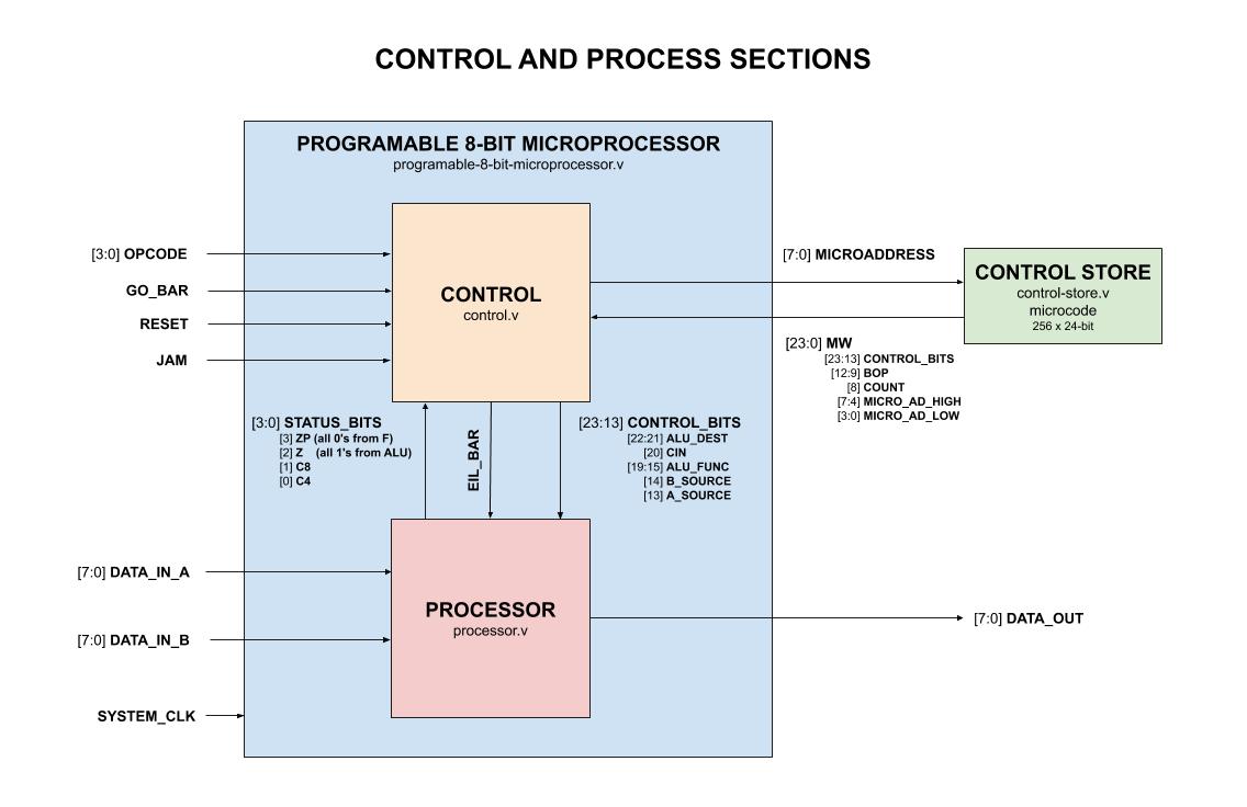
INPUT/OUTPUT
- INPUT
- SYSTEM_CLK
- [3:0] OPCODE
- GO_BAR
- RESET
- JAM
- [7:0] DATA_IN_A
- [7:0] DATA_IN_B
- OUTPUT
- [7:0] DATA_OUT
ARTY S7-50 FPGA DEVELOPMENT BOARD
I burned the microprocessor to an FPGA on an Arty S7-50 FPGA development board.
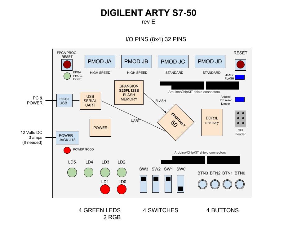
SERVER SIDE (CONNECTION TO RASPBERRY PI)
The FPGA is connected to the Raspberry Pi via the PMOD pins.
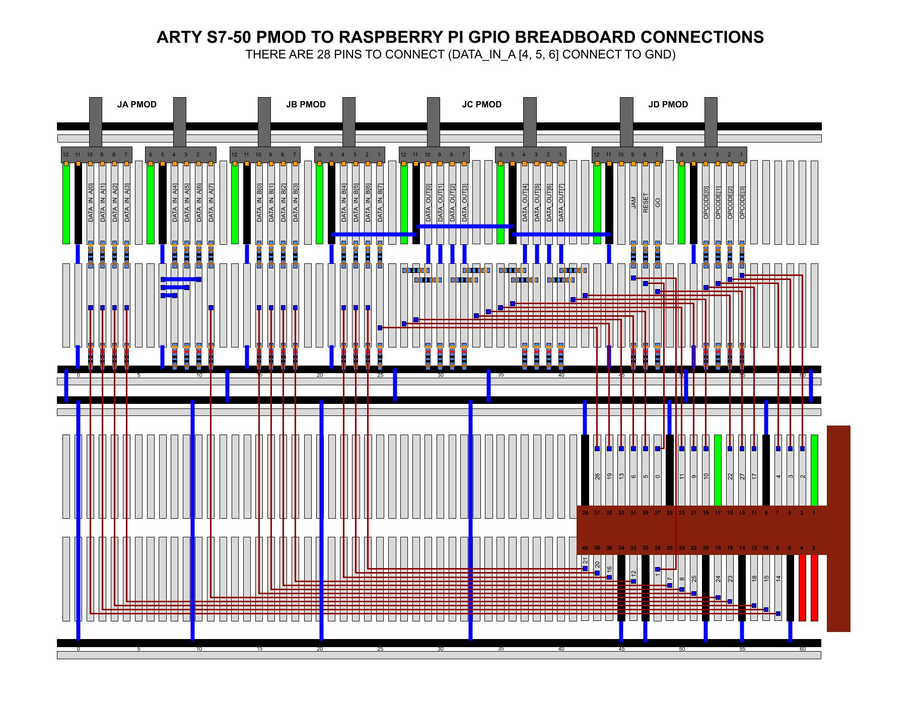
SECTION II - THE BREADBOARD
To connect the Raspberry Pi to the FPGA dev board, I used a breadboard. I connected the GPIO pins on the Raspberry Pi 4B to the PMOD pins on the FPGA development board.
There are a total of 31 pins used by the microprocessor, but there are only 28 GPIO pins. Hence, I tied 3 of the DATA_IN_A pins to gnd.
The pin list between the Raspberry Pi and the FPGA development board is as follows,
| PMOD Pins | RasPi GPIO Pin | |
|---|---|---|
| [7:0] DATA_IN_A | JA PMOD | |
| [7] | 1 | 18 (GPIO24) |
| (GND) [6] | 2 | N/C |
| (GND) [5] | 3 | N/C |
| (GND) [4] | 4 | N/C |
| [3] | 7 | 16 (GPIO23) |
| [2] | 8 | 12 (GPIO18) |
| [1] | 9 | 10 (GPIO15)* |
| [0] | 10 | 08 (GPIO14)* |
| [7:0] DATA_IN_B | JB PMOD | |
| [7] | 1 | 37 (GPIO26) |
| [6] | 2 | 40 (GPIO21) |
| [5] | 3 | 38 (GPIO20) |
| [4] | 4 | 36 (GPIO16) |
| [3] | 7 | 32 (GPIO12) |
| [2] | 8 | 26 (GPIO7) |
| [1] | 9 | 24 (GPIO8) |
| [0] | 10 | 22 (GPIO25) |
| [7:0] DATA_OUT | JC PMOD | |
| [7] | 1 | 15 (GPIO22) |
| [6] | 2 | 19 (GPIO10) |
| [5] | 3 | 21 (GPIO9) |
| [4] | 4 | 23 (GPIO11) |
| [3] | 7 | 29 (GPIO5) |
| [2] | 8 | 31 (GPIO6) |
| [1] | 9 | 33 (GPIO13) |
| [0] | 10 | 35 (GPIO19) |
| [3:0] OPCODE | JD PMOD | |
| [3] | 1 | 03 (GPIO2)** |
| [2] | 2 | 05 (GPIO3)** |
| [1] | 3 | 07 (GPIO4) |
| [0] | 4 | 11 (GPIO17) |
| GO | 7 | 13 (GPIO27) |
| RESET | 8 | 27 (GPIO0) |
| JAM | 9 | 28 (GPIO1) |
| N/C | 10 | N/C |
NOTE1: To use pin 8 (GPIO14) and pin 10 (GPIO15)
you must disable the serial port using raspi-config.
Select Interfacing Options and then
Serial and select No.
NOTE2 Pin 3 (GPIO2) and pin 5 (GPIO3) have fixed pull-up resistors to 3.3V.
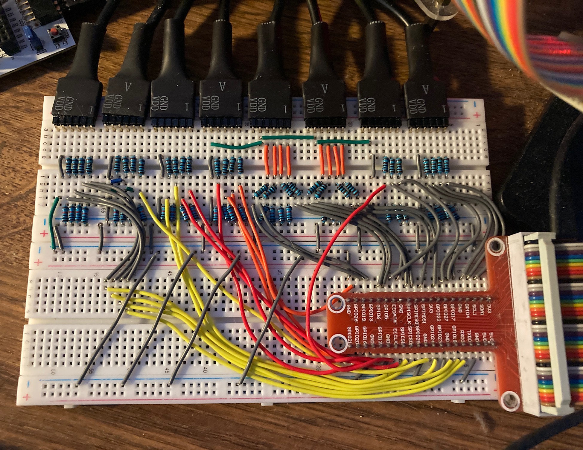
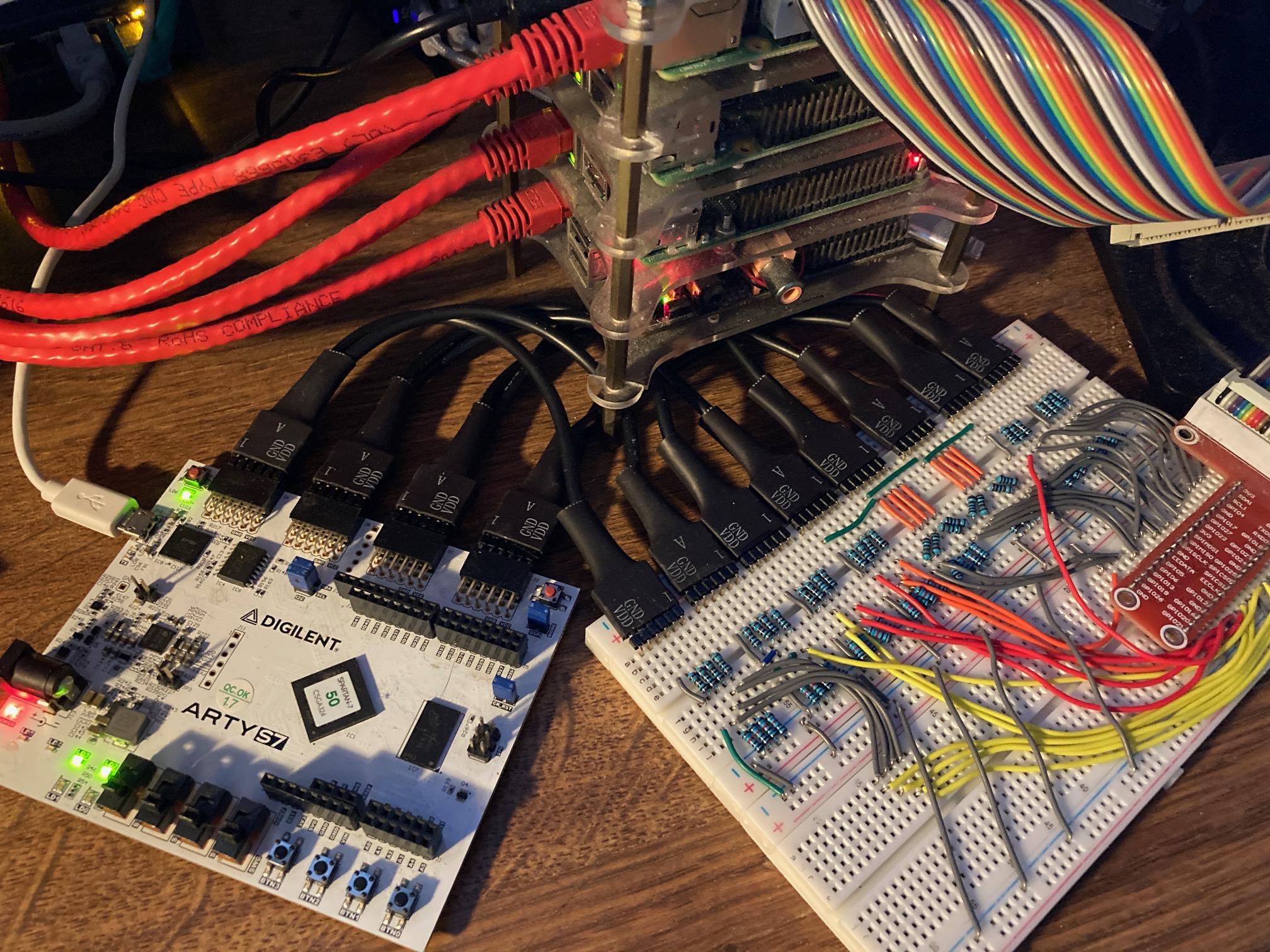
The result,
SECTION III - THE RASPBERRY PI
The Raspberry Pi has two main functions,
- AS A CLIENT - Controls 28 pins of the I/O of the FPGA (GPIO to PMOD) via GO
- AS A SERVER - Provide an interface to the webserver (gRPC)
CLIENT SIDE (CONNECTION TO FPGA)
The Raspberry Pi will control the I/O of the FPGA via the GPIO pins. The Raspberry Pi will be the client and the FPGA will be the server.
CONTROL FPGA I/O VIA GO
The Raspberry Pi will control the FPGA via GO using the periph.io go package.
Init Raspberry Pi,
  // INIT HOST MACHINE (i.e. Raspberry Pi)
  _, err := host.Init()
  if err != nil {
    log.Fatal(err)
  }
For inputs,
  // DATA_IN_A -----------------------------------
  DATA_IN_A7_PIN := gpioreg.ByName("24")
  if DATA_IN_A7_PIN == nil {
    log.Fatal("Failed to find DATA_IN_A7_PIN")
  }
For outputs also set the pulldown resistor,
  // DATA_OUT -----------------------------------
  DATA_OUT_7_PIN := gpioreg.ByName("22")
  if DATA_OUT_7_PIN == nil {
    log.Fatal("Failed to find DATA_OUT_7_PIN")
  }

  // SET PULLDOWN RESISTER AND LOOK FOR BOTH EDGES (High->Low or Low->High)
  err = DATA_OUT_7_PIN.In(gpio.PullDown, gpio.BothEdges)
  if err != nil {
    log.Fatal(err)
  }
SERVER SIDE (CONNECTION TO WEB SERVER)
The Raspberry Pi will also be a server using gRPC. It will accept requests from a web server client and return the results.
GO AND gRPC
tbd
DOCKER (GO INTEGRATION AND DEPLOYMENT)
A go program will interface with both the FPGA and web server. It will placed in a docker image and deployed to a Raspberry Pi 4B.
RUN
To run.sh,
cd section-2-backend-server
go run main.go
Currently, it will ask you if you want to add, subtract, multiply or divide. It will look like,
1: add, 2: subtract, 3: multiply, 4: divide, x: exit: 1
    ADD
    DATA_IN_A: 10000011
    DATA_IN_B: 00001100
    DATA_OUT:  10001111
CREATE BINARY
To create-binary.sh,
cd section-2-backend-server/bin
go build -o control-fpga-via-raspi-and-webserver ../main.go
./control-fpga-via-raspi-and-webserver
This binary will not be used during a docker build since it creates it’s own.
STEP 1 - TEST
To create unit _test files,
cd section-2-backend-server
gotests -w -all main.go
To run unit-tests.sh,
go test -cover ./... | tee test/test_coverage.txt
cat test/test_coverage.txt
STEP 2 - BUILD (DOCKER IMAGE VIA DOCKERFILE)
To build.sh with a Dockerfile,
The Dockerfile has the architecture as arm64,
FROM --platform=linux/arm64 golang:alpine AS builder
You may have to get some libraries,
sudo apt-get install -y qemu qemu-user-static
docker buildx ls
cd section-2-backend-server
docker build --output type=docker\
             --platform=linux/arm64\
             --no-cache\
             -f build/Dockerfile\
             -t jeffdecola/control-fpga-via-raspi-and-webserver .
If you are on an ARM64, you can check and test this docker image,
docker images jeffdecola/control-fpga-via-raspi-and-webserver:latest
docker run --privileged\
           --name control-fpga-via-raspi-and-webserver\
           -dit jeffdecola/control-fpga-via-raspi-and-webserver
Write stdin,
echo '1' | socat EXEC:"docker attach control-fpga-via-raspi-and-webserver",pty STDIN
Check stdout,
docker logs control-fpga-via-raspi-and-webserver
Other commands,
docker exec -i -t control-fpga-via-raspi-and-webserver /bin/bash
docker rm -f control-fpga-via-raspi-and-webserver
In stage 1, rather than copy a binary into a docker image (because that can cause issues), the Dockerfile will build the binary in the docker image,
FROM golang:alpine AS builder
RUN go get -d -v
RUN go build -o /go/bin/control-fpga-via-raspi-and-webserver main.go
In stage 2, the Dockerfile will copy the binary created in
stage 1 and place into a smaller docker base image based
on alpine, which is around 13MB.
STEP 3 - PUSH (TO DOCKERHUB)
You must be logged in to DockerHub,
docker login
To push.sh,
docker push jeffdecola/control-fpga-via-raspi-and-webserver
Check the control-fpga-via-raspi-and-webserver docker image at DockerHub.
STEP 4 - DEPLOY (TO DOCKER ON RASPBERRY PI)
To deploy.sh,
cd section-2-backend-server
docker run --privileged\
           --pull=always\
           --name control-fpga-via-raspi-and-webserver\
            -dit jeffdecola/control-fpga-via-raspi-and-webserver
Using –privileged allows complete access to raspberry pi.
If doing it over the network, you can do something like,
ssh -o StrictHostKeyChecking=no\
    -p 22 jeff@192.168.20.118\
    'export PATH=$PATH:/usr/local/bin; docker run --privileged --pull=always --name control-fpga-via-raspi-and-webserver -dit jeffdecola/control-fpga-via-raspi-and-webserver'
INTERACT WITH DOCKER CONTAINER
The docker container is running on your raspberry pi. As mentioned above, the user may interact with the stdin and stdout of the docker container by,
Write stdin,
echo '1' | socat EXEC:"docker attach control-fpga-via-raspi-and-webserver",pty STDIN
Check stdout,
docker logs control-fpga-via-raspi-and-webserver
CONTINUOUS INTEGRATION & DEPLOYMENT
Refer to ci-README.md on how I automated the above steps.
SECTION IV - THE WEB SERVER
The web server has two main functions,
- AS A CLIENT - It will also receive data from the Raspberry Pi via gRPC
- AS A SERVER - It will handle a request from the browser
CLIENT SIDE (CONNECTION TO RASPBERRY PI)
tbd
SERVER SIDE (CONNECTION TO BROWSER)
php is used to handle the ajax XHR POST call request from the browser.
This is a high level overview of the process,
        // GET THE JSON DATA FROM THE USER
        header("Content-Type: application/json");
        $attributesJSON = json_decode(file_get_contents("php://input"));

        // UN PARSE IT
        $opcode = $attributesJSON->opcode;
        $data_in_a = $attributesJSON->data_in_a;
        $data_in_b = $attributesJSON->data_in_b;
        $go = $attributesJSON->go;

        // DO SOMETHING - THIS IS WHERE YOU WOULD SEND DATA TO THE FPGA
        ...

        // BUILD ARRAY
        $array = [
          'data_out'=>$data_out,
        ];

        // SEND RESPONSE TO THE BROWSER
        echo json_encode($array);
SECTION V - THE BROWSER
I have a working demo at jeffdecola.com/control-an-fpga.
CLIENT SIDE (CONNECTION TO WEB SERVER)
To connect with the webserver, I’m using javascript client side programming. It will send a ajax XHR POST call to the web server.
AJAX XHR POST CALL
On the browser side using javascript, an ajax XHR POST call is made to the web server,
        // PHP FILE LOCATION
        var url = 'path to file/filename.php';

        // CREATE A NEW REQUEST
        postRequest = new XMLHttpRequest();

        // CONVERT JSON TO STRING
        var attributesJSONString = JSON.stringify({
            "opcode": opcode,
            "data_in_a": data_in_a,
            "data_in_b": data_in_b,
            "go": go
        });

        // OPEN CONNECTION - CREATE POST REQUEST
        postRequest.open  'POST' , url, true);

        // SEND JSON FORMAT
        postRequest.setRequestHeader('Content-Type', 'application/json');
        postRequest.send(attributesJSONString);

        // LISTEN AND KICK OFF FUNCTION WHEN READY
        postRequest.onreadystatechange = function() {
            ...see code...
        }
WEBSITE
The end result jeffdecola.com/control-an-fpga looks as follows,